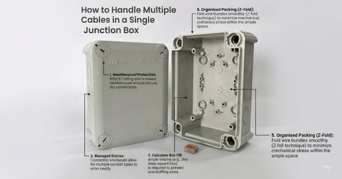
When undertaking a home renovation, adding new power outlets, or upgrading your home’s electrical infrastructure, you will inevitably encounter a common challenge: managing a crowded junction box.A junction box serves as the central hub where different electrical circuits meet, splice, and distribute power to various parts of a building. While connecting two cables is relatively straightforward, executing a junction box electrical wiring project with three, four, or more cables requires meticulous planning, a firm grasp of electrical codes, and the right techniques.
Overcrowded junction boxes, loose wire splices, and poorly insulated connections are among the leading causes of residential electrical fires, arc faults, and frustrating circuit trips. In this definitive guide, we will break down the advanced mechanics of managing multiple cables safely, ensuring your wiring is durable, compliant, and easy to troubleshoot.
1. Understanding the Core Challenges of Multiple Cable Wiring
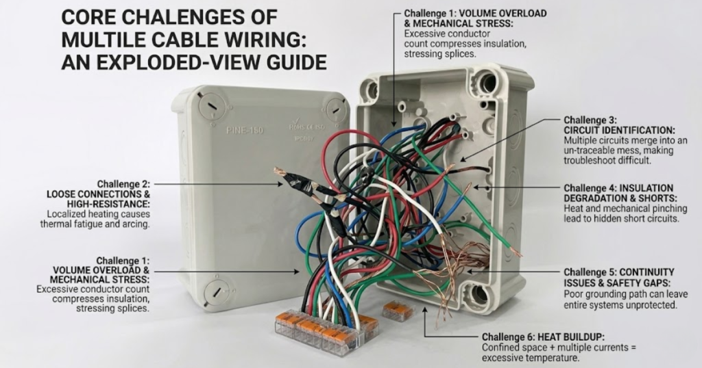
Before stripping any insulation or twisting wires together, it is crucial to understand why managing multiple cables is inherently risky. When multiple electrical currents flow through a single enclosed space, two primary physics principles come into play: heat generation and electromagnetic interference.
- Thermal Accumulation: Every electrical conductor possesses a small amount of resistance. When current flows through it, heat is generated (I^2R losses). In a tight, enclosed space containing twelve or fifteen individual wire conductors, this heat accumulates. If the box is overstuffed, the ambient temperature rises, which can degrade the PVC insulation over time, leading to catastrophic short circuits.
- Physical Crowding and Mechanical Stress: Forcing bulky, stiff copper wires into a small box bends them past their natural bend radius. This places mechanical stress on the wire splices, potentially backing wire nuts off their threads or pulling conductors out of push-in terminals.
- Troubleshooting Complexity: A chaotic jumble of wires makes it nearly impossible to trace a circuit later. If a neutral wire comes loose or a grounding path is interrupted, a clean and organized layout will save hours of dangerous guesswork.
2. Advanced Sizing Calculations: Mastering Box Fill Capacity
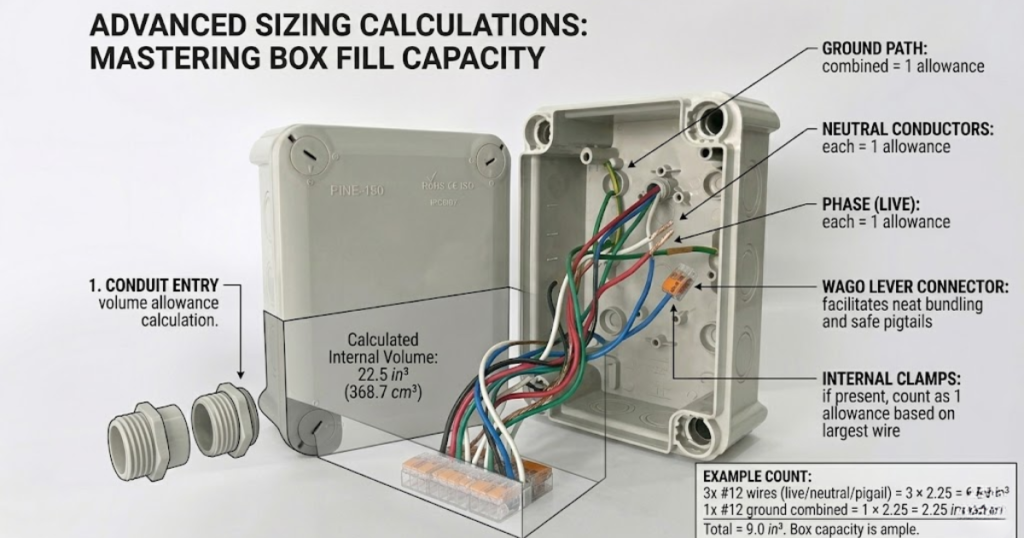
You cannot simply choose a junction box based on visual estimation. Electrical codes globally specify strict guidelines regarding how many conductors can safely reside inside an electrical box based on its interior volume. This is known as Box Fill Capacity.
To ensure your junction box electrical wiring remains safe, you must calculate the total “volume allowance” required by your cables.
The Volume Allowance Breakdown
Each item inside the junction box takes up a specific amount of space, measured in cubic inches (in^3) or cubic centimeters (cm^3).
- Current-Carrying Conductors: Every hot (live) wire and neutral wire entering the box counts as one volume allowance based on its gauge (AWG).
- Grounding Conductors: All grounding wires combined count as only one volume allowance, calculated using the largest ground wire size present in the box.
- Internal Clamps: If the junction box features built-in mechanical cable clamps, add one volume allowance based on the largest wire in the box (regardless of how many clamps there are).
- Devices (Switches/Outlets): If the box houses a switch or a receptacle, each device counts as a double volume allowance based on the size of the wire connected to it.
Wire Size Volume Allowance Table
The following table outlines the volume requirements per conductor according to standard electrical metrics:
| Wire Gauge (AWG) | Common Indian Cross-Section Equivalent | Volume Allowance Required per Wire |
| 14 AWG | Approx 1.5 mm^2 (Lighting Circuits) | 2.00 cubic inches (32.8\text{ }cm^3) |
| 12 AWG | Approx 2.5 mm^2 (Power Outlets/ACs) | 2.25 cubic inches (36.9\text{ }cm^3) |
| 10 AWG | Approx 4.0 mm^2(Heaters/Heavy Load) | 2.50 cubic inches (41.0\text{ }cm^3) |
Step-by-Step Sample Calculation
Imagine you are bringing four 12 AWG cables into a blank junction box (used purely for splicing, with no switches or outlets inside). Each 12 AWG cable contains a Live, a Neutral, and a Ground wire.
- Hot/Live Wires: 4 cables \times 1 wire = 4 conductors \rightarrow 4 \times 2.25 = 9.0\text{ }in^3
- Neutral Wires: 4 cables \times$ 1 wire = 4 conductors \rightarrow 4 \times 2.25 = 9.0\text{ }in^3
- Ground Wires: 4 wires combined = 1 conductor count \rightarrow 1 \times 2.25 = 2.25\text{ }in^3
- Total Volume Required: 9.0 + 9.0 + 2.25 = \mathbf{20.25\text{ }in^3}
Therefore, you must buy a junction box that explicitly states it has an internal volume of at least 20.25 cubic inches. A standard 4-inch square box that is 1.5 inches deep only offers 21\text{ }in^3, which is dangerously close to the limit. In this scenario, upgrading to a deep box (2.125 inches deep, offering 30.3\text{ }in^3) is the professional and safe choice.
3. Choosing the Right Junction Box Material and Type
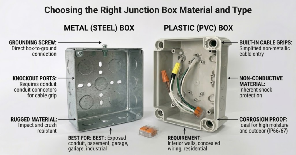
The physical environment of your installation dictates the type of junction box you should deploy. Choosing between plastic (PVC) and metal involves evaluating mechanical protection, grounding needs, and environmental exposure.
Metal Junction Boxes
- Material properties: Usually made of galvanized steel. Extremely rugged and immune to crushing or UV degradation.
- Best Used For: Exposed wiring runs, conduits run through basements, garages, industrial settings, or when using armored/sheathed cables (like metal conduit pipes).
- Crucial Requirement: Metal boxes must be grounded. If a live wire slips loose and touches the interior side of a metal box, the box will become electrified and deliver a fatal shock to anyone touching it unless the box itself is tied to the grounding network via a grounding screw.
Plastic / PVC Junction Boxes
- Material properties: Non-conductive, lightweight, rust-proof, and easy to drill or alter.
- Best Used For: Concealed residential wiring embedded within brick walls, drywall, or ceiling plasterboards using PVC conduits.
- Crucial Requirement: Because PVC does not conduct electricity, you do not need to attach a grounding wire to the body of the box. However, all grounding wires passing through must still be spliced tightly together to maintain continuity for downstream outlets.
4. Preparing the Junction Box and Managing Cable Entry
A chaotic junction box is usually the byproduct of sloppy cable entry. Proper preparation sets the foundation for a neat, maintainable installation.
Knockout Management
Metal and heavy-duty plastic boxes feature pre-punched, circular cutouts called knockouts.
- Only remove the exact number of knockouts required for your incoming cables. Leaving open holes in a junction box allows dust, moisture, and pests (like lizards or insects) to enter, which can bridge contacts and cause short circuits.
- Use a hammer and pliers to cleanly twist away the knockout tab without warping the box casing.
Mechanical Cable Protection
Never pull bare cables through a sharp metal edge.
- For Metal Boxes: Install a cable clamp or a conduit connector into the knockout hole before feeding the wires through. This clamp secures the outer sheath of the cable so that pulling on the exterior conduit does not disturb the sensitive splices inside the box.
- For Plastic Boxes: Ensure the PVC conduit pipes glued into the box entry ports are fitted with smooth adapters or female bushings to eliminate abrasive sharp edges.
Stripping and Length Guidelines
The length of wire you leave inside the box determines how easy it will be to splice.
- The 6-Inch Rule: Ensure that at least 6 inches of free wire conductor extends from the face of the box opening. This gives you enough physical leverage to cleanly hold, twist, and cap the wires.
- Outer Sheath Removal: Strip the outer protective jacket of the multi-core cable back so that only 0.5 to 1 inch of the jacket remains inside the box past the cable clamp. Stripping too much sheath outside the box leaves unprotected individual wires exposed to external damage.
5. Step-by-Step Execution: Splicing Multiple Cables Safely
When dealing with four or more cables, jumping straight into twisting wires will create a bird’s nest. A systematic approach is vital.
[Mains MCB: OFF] ──> [Verify Dead with Tester] ──> [Group Wires by Color] ──> [Splice Earth] ──> [Splice Neutral] ──> [Splice Phase/Live]
Step 1: Isolation and Verification
Before touching a copper wire, switch off the corresponding Miniature Circuit Breaker (MCB) at the main distribution board. Never rely solely on a wall switch, as switches often only break the phase wire, leaving dangerous neutral currents active. Use a Non-Contact Voltage Tester (NCVT) or a digital multimeter directly inside the box across all incoming leads to confirm that zero voltage is present.
Step 2: Sorting and Alignment
Straighten out all individual wire strands. Group them by insulation color code. In India, you will encounter two main color coding schemes depending on the age of the property:
- Modern Indian Standard (IS 4648): Live = Red/Brown, Neutral = Black/Blue, Earth = Green/Yellow.
- Legacy Systems: Live = Red, Neutral = Black, Earth = Green.
Align the wires so they travel parallel to one another. Do not cross live wires over neutral wires randomly within the enclosure.
Step 3: Executing the Ground (Earth) Connections
Always wire your safety paths first. Gather all the green/yellow grounding conductors. Because they are safety wires, their continuity must never fail.
- If you are using a metal junction box, you must integrate a pigtail (a short, 6-inch standalone wire segment). One end of the pigtail fastens securely underneath the green grounding screw on the back wall of the box, and the other end joins the incoming ground wires.
Step 4: Splicing the Neutral Wires
Bring all the neutral wires together. In a multi-cable looping topology, neutrals are tied together to complete the path back to the distribution panel transformer. Cut the copper ends evenly using a precise wire stripper so that no bare copper strands unevenly poke past the rest.
Step 5: Connecting the Phase (Live) Wires
Finally, splice the live wires. If this junction box is feeding separate sub-circuits, ensure you map out which wire goes to which load. Labeling wires with a small piece of masked tape can prevent massive wiring errors at this stage.
Splicing Technologies for Safe Junction Box Electrical Wiring: Wire Nuts vs. Lever Connectors vs. Tape
Traditional Twisting and PVC Electrical Insulation Tape
This is the old-school technique widely practiced by local residential electricians. Wires are twisted using a pair of linesman pliers, and wrapped in vinyl adhesive tape.
- The Danger: Over time, the adhesive on electrical tape dries out due to structural heating cycles. As the tape unravels, bare copper connections are left exposed inside the box. Furthermore, if the twist is not mechanically tight, a micro-gap forms, creating an electrical arc that easily ignites plastic components.
- Best Practice Usage: If you must use this method, execute a tight Lineman’s joint, ensure at least 5 layers of premium-grade, flame-retardant tape (e.g., 3M Scotch or Anchor by Panasonic) wrap past the wire ends, and never use it for high-amperage lines like ACs or geysers.
Twist-On Wire Connectors (Wire Nuts) for Junction Box Electrical Wiring
Wire nuts are plastic caps fitted with an internal tapered metal spring. You push the stripped wire ends into the cap and twist it clockwise. The internal spring cuts small threads into the copper, locking them under mechanical tension.
- Pros: Inexpensive, reliable, requires no tape, and handles up to 4 or 5 wires simultaneously depending on the nut size (indicated by color codes like Yellow or Red).
- Cons: If you mix different wire gauges (e.g., solid 1.5 $mm^2$ wire with stranded 2.5 $mm^2$ wire), the spring may fail to grip the thinner wire evenly.
Lever-Operated Terminal Blocks (e.g., WAGO 221 Series)
Lever connectors represent the gold standard of modern electrical distribution. Instead of twisting wires, you open a small orange lever, insert a cleanly stripped straight wire into the port, and snap the lever down. A internal gas-tight spring clamp locks the wire in place.
- Pros: Zero twisting required. Easily mixes solid and stranded wires. Clear plastic shells let you visually confirm that the copper is fully inserted. Available in 2-port, 3-port, and 5-port configurations, making multiple cable connections incredibly clean.
- Cons: Higher initial material cost compared to wire nuts or tape.
7. Organizing and Packing the Wires (The Accordion Technique)
Once all splices are safely locked into wire nuts or lever connectors, the final mechanical challenge is pushing them into the box without pinching insulation or dislodging connections.
Never use the butt end of a screwdriver to forcefully cram wires into a box. This can shear copper conductors or gouge plastic insulation. Instead, use the Accordion Fold (Z-Fold) method:
Step A: Push the wire splice connector straight back toward the rear wall of the box.
Step B: Bend the incoming conductors smoothly into a alternating “Z” or “S” shape.
Step C: Tuck the loops along the perimeter edges of the box interior.
Comprehensive Troubleshooting Matrix
| Symptom | Probable Root Cause | Corrective Action Required |
| Junction box lid feels warm or hot to the touch. | Overloaded circuit or a high-resistance loose connection generating thermal dissipation. | Turn off MCB immediately. Check for loose wire nuts, burnt insulation tape, or overloaded appliances drawing excess current. |
| Circuit breaker trips immediately when power is restored. | A bare live wire is touching a neutral wire or the grounded metal casing of the box. | Re-open the box. Inspect all splices for exposed copper strands poking out from underneath connectors. |
| Connected downstream lights flicker intermittently. | A loose connection inside the junction box, often caused by poor mechanical wire twisting. | Replace old tape joints with modern spring-loaded lever connectors or high-quality wire nuts. |
Frequently Asked Questions (FAQs)
Q1: Can I mix copper wires of different sizes (gauges) in one junction box?
Yes. You can mix different wire sizes (e.g., 1.5 $mm^2$ for lighting triggers and 2.5 $mm^2$ for main power feeds) within the same junction box, provided the box volume is large enough to handle the total capacity.
Q2: Is it legally permissible to hide a junction box inside a closed ceiling or drywall?
Absolutely not. According to standard electrical codes (including the National Electrical Code and Indian safety regulations), all junction boxes must remain permanently accessible. You cannot plaster over a junction box, cover it with permanent wood paneling, or hide it behind a structural drywall sheet. If a splice fails, technicians must be able to locate and service the box without destroying architectural elements. Use an aesthetically neat blank cover plate to keep it accessible.
Q3: How many cables can I safely bring through a single knockout hole?
As a general safety standard, you should only bring one multi-core cable through a single cable clamp or knockout connector. Shoving two or more cables through a single tightly clamped entry port can pinch the cables against each other, crushing the inner insulation layers and causing a hidden short circuit inside the conduit entry point.
Q4: Should I twist stranded wires before putting them into a lever connector?
No. Lever connectors (like WAGO blocks) are designed to work with straight, untwisted conductors. If you twist stranded wire strands before inserting them, the spring clamp cannot distribute its mechanical tension evenly across all the delicate copper filaments. Strip the wire cleanly, keep the strands straight, insert, and snap the lever down.
Q5: What happens if a neutral wire comes loose in a multiple-cable junction box?
If a common neutral wire comes loose in a junction box serving multiple circuits, it can cause an open-neutral fault. This can result in downstream appliances failing to turn on, or worse, it can create unbalanced voltages across circuits, causing delicate electronics (like LED TVs or computers) to burn out due to over-voltage spikes.